Recents in Beach

ALTERNATOR


    INTRODUCTION   

     An alternator is an electromechanical device that converts mechanical energy to electrical energy in the form of alternating current. Synchronous generators are also called as alternators.
     A.C. generators are used in to generate electricity in hydroelectric and thermal plants. Alternators are also used in automobiles to generate electricity. 

    Like a D.C. generator, an alternator also has an armature winding and a field winding.  But there is one important difference between the two. 
      • In D.C. generators, the field poles are stationary and the armature conductors rotate. The voltage generated in the armature conductors is of alternating nature. This generated alternating voltage is converted to a direct voltage at the brushes with the help of the commutator.
      • But in the synchronous generator it is convenient and advantageous to place the field winding on the rotating part (i.e., rotor) and armature winding on the stationary part (i.e., stator). No commutator is required in an alternator.


    ADVANTAGES OF STATIONARY ARMATURE   

    Most alternators have the rotating field and the stationary armature. The rotating-field type alternator has several advantages over the rotating-armature type alternator. 
    1.  A stationary armature is more easily insulated for the high voltage for which the alternator is designed. This generated voltage may be as high as 33K V. 
    2.  The armature windings can be fixed better mechanically against high electro- magnetic forces due to large short-circuit currents when the armature windings are in the stator. 
    3.  The armature windings, being stationary, are not subjected to vibration and centrifugal forces. 
    4.  The output current can be taken directly from fixed terminals on the stationary armature without using slip rings, brushes, etc. 
    5.  Only two slip rings are required for d.c. supply to the field winding on the rotor.  
    6.  The stationary armature may be cooled more easily because the armature can be made large to provide a number of cooling ducts. 


    TYPES OF SYNCHRONOUS MACHINES   

    According to the arrangement of armature and field winding, the synchronous machines are classified as rotating armature type or rotating field type 

    ➢  In rotating armature type the armature winding is on the rotor and the field winding is on the stator. The generated EMF or current is brought to the load via the slip rings. These type of generators are built only in small units.  
    ➢  In case of rotating field type generators field windings are on the rotor and the armature windings are on the stator. Here the field current is supplied through a pair of slip rings and the induced EMF or current is supplied to the load via the stationary terminals. 


    Based on the type of the prime movers employed the synchronous generators are classified as  
    1.  Hydro generators: The generators which are driven by hydraulic turbines are called hydro generators. These are run at lower speeds less than 1000 rpm.  
    2.  Turbo generators: These are the generators driven by steam turbines. These generators are run at very high speed of 1500rpm or above.  
    3.  Engine driven Generators: These are driven by IC engines. These are run at a speed less than 1500 rpm.  


    CONSTRUCTION OF ALTERNATOR   

    An alternator consists of two main parts namely, the 
    i. Stator 
    ii. Rotor  

    The stator is the stationary part of the machine. It carries the armature winding in which the voltage is generated. The output of the machine is taken from the stator. The rotor is the rotating part of the machine. The rotor produces the main field flux. 

                                                   
    Construction Figure
    Construction Figure of Alternator


    Stator Construction: 
    The Stationary part of the alternator is known as stator. It provides housing and support for the rotor. Stator is built up of sheet-steel laminations having slots on its inner periphery. A 3- phase winding is placed in these slots and serves as the armature winding of the alternator. The armature winding is always connected in star and the neutral is connected to ground.  The stator is the outer stationary part of the machine, which consists of  
    •  The outer cylindrical frame called yoke, which is made either of welded sheet steel, cast iron. 
    •  The magnetic path, which comprises a set of slotted steel laminations called stator core pressed into the cylindrical space inside the outer frame. The magnetic path is laminated to reduce eddy currents, reducing losses and heating. 


    Rotor Construction: 
    The rotor carries a field winding which is supplied with direct current through two slip rings by a separate D.C. source. This D.C. source (called exciter) is generally a small D.C. shunt or compound generator mounted on the shaft of the alternator. There are two types of rotor constructions namely, 
    i. Salient(or projecting) pole type 
    ii. Non salient (or Cylindrical) pole type. 

    Salient (or projected) pole type: 
    •  The pole is made of steel or cast iron and the pole winding is excited by a D.C. generator driven by the shaft of alternator. 
    •  These type of machines have salient pole or projecting poles with concentrated field windings. This type of construction is for the machines which are driven by hydraulic turbines or Diesel engines. 
    •  The salient pole type of rotor is used for low to medium speed/rpm alternators, where more number of poles are required may be 20 or 30 poles.  
    •  A salient pole alternator can be identified by large diameter and short axial length. The large diameter accommodates a large number of poles. 
    •  A salient-pole synchronous machine has a non-uniform air gap. The air gap is minimum under the pole centers and it is maximum in between the poles. 
    •  Salient-pole alternators driven by water turbines are called hydro-alternators or hydro-generators. 
                                                         
    salient pole type


    Damper windings are provided in the pole faces of salient pole alternators. Damper windings are nothing but the copper or aluminum bars housed in the slots of the pole faces. These damper windings are serving the function of providing mechanical balance; provide damping effect, reduce the effect of over voltages and damp out hunting in case of alternators.  


    Non salient (or cylindrical or Round) pole type: 
    •  The rotor is made of steel   cylinder with number of slots cut on the periphery of the cylinder. The field windings are placed in the slots. 
    •  These machines are having cylindrical smooth rotor construction with distributed field winding in slots.  
    •  Cylindrical pole type of rotor construction is employed for the machine driven by steam turbines.  
    •  These cylindrical pole type alternators have large axial length and smaller diameter. 
    •  Cylindrical rotors are particularly useful in high-speed machines. The cylindrical rotor type alternator has two or four poles on the rotor. Such a construction provides a greater mechanical strength and permits more accurate dynamic balancing. 
    •  The cylindrical rotor machine makes less windage losses and the operation is less noisy because of uniform air gap. 
                                               
    non-salient type


     WORKING PRINCIPLE OF ALTERNATOR    


    An alternator operates on the same fundamental principle of electromagnetic Induction as a D.C. generator i.e., when the flux linking a conductor changes, an E.M.F is induced in the conductor. Field windings are the windings producing the main magnetic field (rotor windings for synchronous machines); armature windings are the windings where the main voltage is induced (stator windings for synchronous machines). The rotor winding is energized from the D.C exciter to produce a rotor magnetic field and alternate N and S poles are developed on the rotor. When the rotor is rotated in anti- clockwise direction by a prime mover, the stator or armature conductors are cut by the magnetic flux of rotor poles. Consequently, E.M.F is induced in the armature conductors due to electromagnetic induction. The induced E.M.F is alternating since N and S poles of rotor alternately pass the armature conductors. The direction of induced E.M.F can be found by Fleming’s right hand rule and frequency is given by; 
               f=(PN)/120 where, 
                                       N= speed of rotor in r.p.m
                                       P= Number of rotor poles
                                        f= Frequency in Hz

    When the rotor is rotated, a 3-phase voltage is induced in the armature winding. The magnitude of induced E.M.F depends upon the speed of rotation and the D.C exciting current. The magnitude of E.M.F in each phases of the armature winding is the same.  


    So the question rise that, what is difference between alternator and generator?

    Differentiating Property

    Alternator

    Generator

    Definition

    An alternator is a machine that converts mechanical energy into electrical energy(AC).

    A generator is a mechanical device which converts mechanical energy to electrical energy(either AC or DC).

    Generated current/Output current

    An alternator always induces an alternating current.

    A generator can generate either alternating or direct current.

    Efficiency

    Alternators are very efficient.

    Generators are less efficient.

    Output

    Alternators have a higher output than generators.

    Generators have a lower output than an alternator.

    Energy Conservation

    Alternators use only the required amount of energy, so it conserves more energy.

    Generators use all the energy that being produced and so, it is conserve less energy.

    Magnetic Field

    The magnetic field is rotating inside the stator of an alternator.

    In case of a generator, the magnetic field is stationary or fixed where the armature winding spins.

     Movement of Armature

    The armature of an alternator is stationary.

    But here, the armature of a generator is rotating.

    Input Supply

    The alternator takes input supply from the stator.

    The generator takes input supply from the rotor.

    Rotation Per Minute Range

    Alternators have a wide range of RPM.

    Here it have a low range of RPM.

    Voltage Generation

    Alternators produce voltage only when it requires.

    Generators produce voltage every times.

     After Installation

    Polarization is not required after installation.

    Generators need to be polarized after installation.

    Size

    Alternators are generally smaller in size.

    Generators are larger and require more space to fit in. thus it is bigger than an alternator.

    Brush Efficiency

    In case Alternator, Brushes last longer

    But in generator, it didn’t last that much of an alternator.

    Charging of a dead battery?

    No, it can’t charge dead battery(never)

    But a generator can be used to charge a dead battery

    Uses

    Alternators are mainly used in the automobile industry

    Generators are widely used to produce large-scale electricity.

    Why used?

    Alternators are used in automobile industry because it works charging system for the battery.

    Generator are used to produce electricity because it can produce larger amount i.e. large-scale.


    RELATION BETWEEN SPEED AND FREQUENCY     

    The frequency of induced E.M.F in the armature conductors depends upon speed &the number of poles. 
    Let N=rotor speed in r.p.m        
    P= number of rotor poles        
    f =frequency of E.M.F in HZ  
    ❖  Armature (stator) conductor successively swept by N &S poles of the rotor. If a positive voltage is induced when a N-pole sweeps across the conductor, similarly negative voltage is induced when a S-pole sweeps by. 
     
    That is one complete cycle of E.M.F is generated in the conductor as a pair of poles passes it i.e., one N-pole and the adjacent following S-pole.  

    No. of cycles/revolution = No. of pair of poles = P/2 
    No. of revolution/second =N/60 
    No. of cycles/second = (P/2)(N/60) 
    But no. of cycles of E.M.F per second is its frequency. 

    So, f=(PN)/120  where, 
                                    N= speed of rotor in r.p.m
                                    P= Number of rotor poles
                                     f= Frequency in Hz.

    For a given alternator, P is fixed, therefore, the alternator must be run at synchronous speed to give an output of desired frequency. For this reason the alternator is also called as synchronous generator


    TERMINOLOGY IN ARMATURE WINDING     

      
    Conductor: Each individual length of wire lying in the magnetic field is called conductor.
      
    Turn: When the two conductors lying in the magnetic field are connected in series, so that the emf induced in them help each other or the resultant induced emf becomes double of that due to one conductor is called turn.  

    Coil: When one or more turns are connected in series and two ends of it are connected to the adjacent commutator segments it is called a coil. 
                                                   
    different types of Coil


    Pole Pitch: A pole pitch is defined as the peripheral distance between two adjacent poles. 
                                                              Or 
    The pole pitch is defined as distance is measured in term of armature slots or armature conductors per pole. Pole pitch is always equal to 180° electrical

    Coil Span or Coil Pitch: The distance between the two coil-sides of a coil is called coil-span or coil- pitch. It is usually measured in terms of teeth, slots or electrical degrees. 


    Windings in Alternators: 
    In case of three phase alternators the following types of windings are employed. 

    ❖  Based on type of winding connections, the armature winding of Alternator are of two types.
    •  Lap winding.  
    •  Wave winding.

    ❖ Based on pitch of the coil-  
    •  full pitched.  
    •  short pitched. 

    ❖ Based on number of layers-  
    •  Single layer.  
    •  Double layer.  

    ❖ Based on distribution of windings- 
    •  Concentrated winding. 
    •  Distributed winding. 


    Based on type of winding connection-

    Lap winding of an Alternator: 
    In this type of winding the finishing end of one coil is connected to a commutator segment and to the start end of adjacent coil located under the same pole and similarly all coils are connected. 
    This type of winding is known as lap because the sides of successive coils overlap each other. The purposes of such type of windings are, 
    a)  To increase the number of parallel paths enabling the armature current to increase i.e., for high current output. 
    b)  To improve commutation as the current per conductor decreases. 

                                          Lap winding


    Wave winding of Alternator: 
    In wave winding the coils which are carrying current in one direction are connected in series circuit and the carrying currents in opposite direction are connected in another series circuit. In wave winding, the conductors are so connected that they are divided into two parallel paths irrespective of the number of poles of the machine. Thus, if the machine has Z armature conductors, there will be only two parallel paths each having Z/2 conductors in series. In this case number of brushes is equal to two, i.e. number of parallel paths.  

                                     wave winding


    Based on pitch of the coil-  

    Full Pitched Coil: 
    If the coil-span (or coil-pitch) is equal to the pole-pitch, then the coil is termed a full-pitch coil. In this situation, two opposite sides of the coil lie under two opposite poles. Hence E.M.F induced in one side of the coil will be in 180˚ phase shift with E.M.F induced in the other side of the coil. Thus, the total terminal voltage of the coil will be the arithmetic sum of these two E.M.F.  
                                                                
    full pitch coil


    Short Pitched Coil: 
    If the coil span is less than the pole pitch, then the winding is referred as short pitched coil or fractional pitched. In this coil, there will be a phase difference between induced E.M.F in two sides, less than 180 ˚. Hence resultant terminal voltage of the coil is vector sum of these two E.M.F and it is less than that of full-pitched coil.
                                                                   
    short pitched coil


    Based on number of layers-

    Single layer:
                                              
    single layer winding


    Double layer:
                                      
    double layer winding


    Based on distribution of windings-

    Concentrated Winding:
    ❖ A winding with only one slot per pole per phase is called a concentrated winding. 
    ❖ In this type of winding, the E.M.F generated/phase is equal to the arithmetic sum of the individual coil E.M.F in that phase. 

    Examples of concentrated winding are
    ➢ field windings for salient-pole synchronous machines 
    ➢ D.C. machines 
    ➢ Primary and secondary windings of a transformer


    Distributed winding: 
    ❖ If the coils/phase are distributed over several slots in space, then it is called distributed winding. 
    ❖  The E.M.F in the coils are not in phase (i.e., phase difference is not zero) but are displaced from each by the slot angle α (The angular displacement in electrical agrees between the adjacent slots is called slot angle).  
    ❖ The E.M.F/phase will be the phasor sum of coil E.M.F.

    Examples of distributed winding are 
    ➢ Stator and rotor of induction machines 
    ➢ The armatures of both synchronous and D.C. machines


    WINDING FACTOR     

    Pitch Factor: 
    The ratio of phasor (vector) sum of induced emfs per coil to the arithmetic sum of induced emfs per coil is known as pitch factor (Kp) or coil span factor (Kc) which is always less than unity. 

    Expression for Kp. 
    Consider a coil AB which is short-pitch by angle β electrical degrees. The E.M.F generated in the coil sides A and B differ in phase by an angle b and can be represented by phasors 𝐸 𝐴and 𝐸 𝐵 respectively. The diagonal of the parallelogram represents the resultant E.M.F  𝐸 𝑅 of the coil. 


    Distribution Factor: 
    A winding with only one slot per pole per phase is called a concentrated winding. In this type of winding, the E.M.F generated/phase is equal to the arithmetic sum of the individual coil E.M.F in that phase.  However, if the coils/phase are distributed over several slots in space (distributed winding), the E.M.F in the coils are not in phase (i.e., phase difference is not zero) but are displaced from each by the slot angle α. The E.M.F/phase will be the phasor sum of coil E.M.F  
    The ratio of the phasor sum of the E.M.F induced in all the coils distributed in a number of slots under one pole to the arithmetic sum of the E.M.F induced(or to the resultant of E.M.F induced in all coils concentrated in one slot under one pole) is known as breadth factor (Kp) or distribution factor (Kd).The distribution factor is always less than unity. 


    Example 1:- Calculate the distribution factor for a 36-slots, 4 pole, single layer three phase winding.
    Solution2


    Example 2:- The Stator winding of an alternator has 48 slots. A 4 pole, 3 phase winding is made on the stator. Each Coil spans 11 slots. Calculate the Pitch factor.
    Solution2


    Example 3:- Calculate the Distribution factor for a single phase alternator having 6 slots/pole-
    (I) When all the slots are wound and
    (II) When only four adjacent slots per pole are wound the remaining slots being unwound.
    solution3

      
    Example 4:- An Alternator has 9 slots/pole. If each Coil spans 8 slots pitches, what is the value of the Pitch factor?
    Solution4


    Example 5:- The Stator of a 3-Phase Alternator has 9 slots per pole and carries a balanced 3-Phase, double winding. The coils are Short-pitched and the coil pitch is 7 slots. Find the distribution factor & pitch factor.
    Solution5


    Q1. Calculate the pitch factor for a winding having 24 stator slots when the coil spans 5 slots.

                         
    Q1 ans


    Q2. A certain alternator has 6 slots per pole and the coils are short pitch by 1 slot. What is the value of pitch factor?
    Q2 ans


    Q3. Calculate the value of distribution factor for a 3-phase alternator having 12 slots per pole.
    Q3 ans


    Q4. Calculate the distribution factor for a 36 slot, 4 pole, single layer, 3-phase winding.
    Q4 ans


    Q5. A part of an alternator winding consists of six coils in series, each coil having an emf of 10V r.m.s induced in it. The coils are placed in successive slots and between each slot and the next, there is an electrical phase displacement of 30 °. Find graphically or by calculation the emf of the six coils in series. 
    Q5 ans


    EQUATION OF INDUCED E.M.F     

    Let,           Z= No. of conductors or coil sides in series/phase
                       = 2T                - where T is the No. of coils or turns per phase
                     P= No. of Poles
                      f= frequency of induced e.m.f in Hz
                     ϕ= flux/pole in webers
                  K𝒹= distribution factor= [{sin(nα/2)}/{n×sin(α/2)}]
         K𝒸 or Kp= pitch or coil span factor= cos(β/2)
                     K𝒻= form factor = 1.11
                       N= rotor r.p.m

    In one revolution of the rotor each stator conductor is cut by a flux of ϕP webers.
    ∴             dϕ=ϕP and dt= 60/N second
    Average e.m.f induced per conductor= dϕ/dt= (ϕP)/(60/N)= ϕNP/60


    Example 1:-  A 3-phase, 6-pole, star connected alternator revolves at 1000 rpm. the stator has 90 slots and 8 conductors per slot. The flux per pole is 0.05 Wb (Sinusoidally wave). Calculate the voltage generated by the machine if the winding factor is 0.96


    Example 2:-  A 3-Phase, 16 pole synchronous generator has a resultant air gap flux of 0.06 Wb per pole. The flux is sinusoidally distributed over the pole. The stator has a 2 slots per pole per phase and 4 conductors per slots are accommodated in two layers. The coil span is 150 degree electrical. Calculate the phase & line induced voltage when the machine runs at 375 rpm.


    Q1. A 3-Phase, 16 pole alternator has a star-connected winding with 144 slots and 10 conductors per slot. The flux per pole is 0.03 Wb, Sinusoidally distributed and the speed is 375 rpm. Find the frequency rpm and the phase and line emf. Assume full pitched coil.


    Q2. Find the no load phase and the line voltage of a star connected 3-Phase, 6 pole alternator which runs at 1200 runs at 1200 rpm, having flux per pole of 0.1 Wb sinusoidally distributed. Its stator has 54 slots having double layer winding. Each coil has 8 turns and the coil is chorded by 1 slot.


    Q3. A 3-Phase, 4 pole, 50 Hz, Star connected alternator has 60 slots, with 2 conductors per slot & having armature winding of the two layer type. Coils are short-pitched in such a way that if one coil side lies in slot number 1, the other lies in slot number 13. Determine the useful flux per pole required to generate a line voltage of 6000V.


    Q4. A 6 pole alternator rotating at 1000 rpm has a single phase winding housed in 3 slots per pole, the slots in groups of three being 20° apart. If each slot contains 10 conductors and the flux per pole is 2×10⁻²Wb. Calculate the voltage generated, assuming the flux distribution to be sinusoidal.

    Q5. Find the no-load phase and line voltage of a star-connected, 4-pole alternator having flux per pole of 0.1 Wb sinusoidally distributed; 4 slots per pole per phase, 4 conductors per slot, double-layer winding with a coil span of 150° .


    Q6. 3-Φ, 10-pole, Y-connected alternator runs at 600 r.p.m. It has 120 stator slots with 8 conductors per slot and the conductors of each phase are connected in series. Determine the phase and line e.m.fs. if the flux per pole is 56 mWb. Assume full-pitch coils.


    Q7. Calculate the speed and open-circuit line and phase voltages of a 4-pole, 3-phase, 50-Hz, star-connected alternator with 36 slots and 30 conductors per slot. The flux per pole is 0.0496 Wb and is sinusoidally distributed. 


    Q8. A 4-pole, 3-phase, star connected alternator armature has 12 slots with 24 conductors per slot and the flux per pole is 0.1 Wb sinusoidally distributed. calculate the line e.m.f generated at 50 Hz.


    Q9. A 3-phase, 16-pole alternator has a star-connected winding with 144 slots and 10 conductors per slot. The flux per pole is 30mWb sinusoidally distributed. Find the frequency, the phase and line voltages if the speed is 375 rpm.


    Q10. A synchronous generator has 9 slots per pole. if each coil spans 8 slot pitches, what is the value of the pitch factor.


    HARMONICS      

    Harmonics are unwanted higher frequencies which superimposed on the fundamental waveform creating a distorted wave pattern. The sources of harmonics in the output voltage waveform are the non- sinusoidal waveform of the field flux. 

    When the uniformly sinusoidal distributed air gap flux is cut by either the stationary or rotating armature sinusoidal EMF is induced in the alternator. Hence the nature of the waveform of induced EMF and current is sinusoidal. But when the alternator is loaded waveform will not continue to be sinusoidal or becomes non sinusoidal. Such non sinusoidal wave form is called complex wave form. 
    By using Fourier series representation, it is possible to represent complex non sinusoidal waveform in terms of series of sinusoidal components called harmonics, whose frequencies are integral multiples of fundamental wave.

    The fundamental wave form is one which is having the frequency same as that of complex wave. The waveform, which is of the frequency twice that of the fundamental is called second harmonic. The one which is having the frequency three times that of the fundamental is called third harmonic and so on. These harmonic components can be represented as follows.

    Fundamental: e1 = Em1 Sin (ωt ± θ1)  
    2nd Harmonic e2 = Em2 Sin (2ωt ± θ2)  
    3rd Harmonic e3 = Em3 Sin (3ωt ± θ3)  
    5th Harmonic e5 = Em5 Sin (5ωt ± θ5) etc.  

    In case of alternators as the field system and the stator coils are symmetrical the induced EMF will also be symmetrical and hence the generated EMF in an alternator will not contain any even harmonics. 

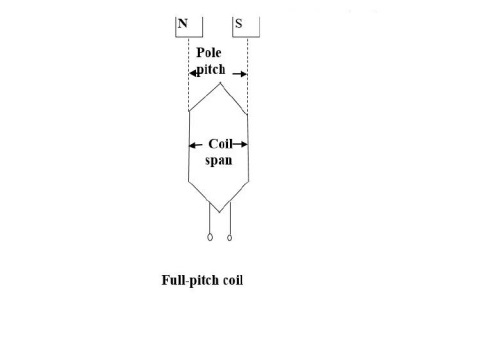
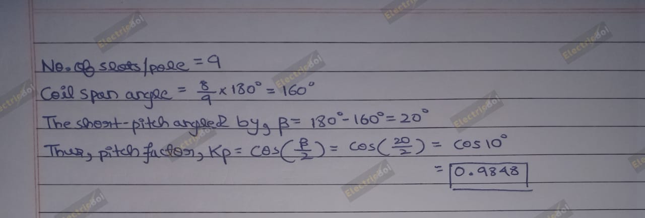
    Q1. An alternator has 18 slots/pole and the first coil lies in slot 1 and 16. Calculate the pitch factor for (i) fundamental
                              (ii) 3rd Harmonic
                             (iii) 5th Harmonic
                             (iv) 7th Harmonic


    ARMATURE REACTION IN ALTERNATOR       

    When an alternator is running at no-load, there will be no current flowing through the armature winding and the flux produced in the air-gap will be only due to the rotor ampere- turns.
    When load current flows through the armature windings of an alternator, the resulting mmf produces flux. This armature flux reacts with the main-pole flux, causing the resultant flux to become either less than or more than the original main flux.
      
    The effect of the armature (stator) flux on the flux produced by the rotor field poles is called armature reaction
    .  
    Two things are worth noting about the armature reaction in an alternator.  
    • First, the armature flux and the flux produced by rotor ampere-turns rotate at the same speed (synchronous speed) in the same direction and, therefore, the two fluxes are fixed in space relative to each other. 
    • Secondly, the modification of flux in the air-gap due to armature flux depends on the magnitude of stator current and on the power factor of the load. It is the load power factor which determines whether the armature flux distorts, opposes or helps the flux produced by rotor ampere-turns. 

    To illustrate this important point, we shall consider the following three cases:  
                1. When load P.f. is unity
                2. When load P.f. is zero lagging. 
                3. When load P.f. is zero leading. 

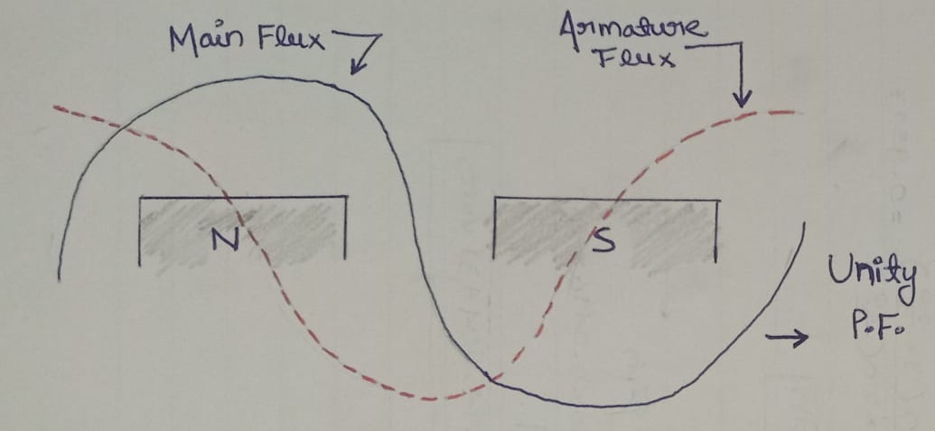
    When load Power factor is unity
    Since the armature is on open-circuit, there is no stator current and the flux due to rotor current is distributed symmetrically in the air-gap. Since the direction of the rotor is assumed clockwise, the generated e.m.f. in phase R₁R₂ is at its maximum and is towards the paper in the conductor R₁ and outwards in conductor R₂. No armature flux is produced since no current flows in the armature winding. 

    According to right hand rule, the current is “in” in the conductors under N-pole and “out” in the conductors under S-pole. Therefore, the armature flux is clockwise due to currents in the top conductors and anti clockwise due to currents in the bottom conductors. The armature flux is at 90° to the main flux (due to rotor current) and is behind the main flux. In this case, the flux in the air-gap is distorted but not weakened. Therefore, at unity p.f., the effect of armature reaction is merely to distort the main field; there is no weakening of the main field and the average flux practically remains the same. Since the magnetic flux due to stator currents (i.e., armature flux) rotate; synchronously with the rotor, the flux distortion remains the same for all positions of the rotor.  
    When load power factor is unity


    When load Power factor is Zero lagging
    When a pure inductive load (zero P.f. lagging) is connected across the terminals of the alternator, current lags behind the voltage by 90°. This means that current will be maximum at zero e.m.f. and vice-versa. 
    When the alternator is supplying a pure inductive load, the current in phase R₁R₂ will not reach its maximum value until N-pole advanced90° electrical 

    Now the armature flux is from right to left and field flux is from left to right.All the flux produced by armature current (i.e., armature flux) opposes the field flux and, therefore, weakens it. In other words, armature reaction is directly demagnetizing. Hence at zero P.f. lagging, the armature reaction weakens the main flux. This causes a reduction in the generated e.m.f.
    When load power factor is zero lagging


    When load Power factor is Zero leading
    When a pure capacitive load (zero P.f. leading) is connected across the terminals of the alternator, the current in armature windings will lead the induced e.m.f. by 90°. The effect of armature reaction will be the reverse that for pure inductive load. Thus armature flux now aids the main flux and the generated e.m.f. is increased. When alternator supplying resistive load ,e.m.f. as well as current in phase R₁R₂ is maximum in the position.

    When the alternator is supplying a pure capacitive load, the maximum current in R₁R₂ will occur 90° electrical before the occurrence of maximum induced e.m.f. Therefore, maximum current in phase R₁R₂ will occur if the position of the rotor remains 90° behind as compared to its position under resistive load.

    It is clear that armature flux is now in the same direction as the field flux and, therefore, strengthens it. This causes an increase in the generated voltage. Hence at zero P.f. leading, the armature reaction strengthens the main flux. 
    When load power factor is zero leading


    ALTERNATOR ON LOAD     

    When the load on the alternator is increased (i.e., armature current Ia is increased), the field excitation and speed being kept constant, the terminal voltage V (phase value) of the alternator decreases. This is due to 
    i. Voltage drop 𝐼𝑎𝑅𝑎 where 𝑅𝑎 is the armature resistance per phase.
    ii. Voltage drop 𝐼𝑎𝑋𝐿 where 𝑋𝐿 is the armature leakage reactance per phase. 
    iii. Voltage drop because of armature reaction.  

    i. Armature Resistance (Rₐ) 
    Since the armature or stator winding has some resistance, there will be an IₐRₐ drop when current (Iₐ) flows through it. The armature resistance per phase is generally small so that 𝐼ₐ𝑅ₐ drop is negligible for all practical purposes.
     
    ii. Armature Leakage Reactance (XL)
     When current flows through the armature winding, flux is set up and a part of it does not cross the air-gap and links the coil sides. This leakage flux alternates with current and gives the winding self-inductance. This is called armature leakage reactance. Therefore, there will be  𝐼𝑎𝑋𝐿 drop which is also effective in reducing the terminal voltage. 

    iii. Armature reaction
     The load is generally inductive and the effect of armature reaction is to reduce the generated voltage. The armature reaction effect is accounted for by assuming the presence of a fictitious reactance Xₐᵣ in the armature winding. The quantity Xₐᵣ is called reactance of armature reaction. The value of IₐXₐᵣ represents the voltage drop due to armature reaction. 

    Load on Unity
    Unity power factor load


    load on lagging
    Lagging power factor load


    load on leading
    leading power factor load


    Q1:- A 500 kVA, 3-Phase, star connected alternator has a rated line-to-line voltage of 3300V. The resistance and synchronous reactance per phase are 0.3 ohm and 4 ohm respectively. calculate the line value of the e.m.f generated at full-load, 0.8 p.f. lagging.


    Q2:- A 1000 kVA, 2300V, 3-phase, star-connected alternator has a resistance of 0.309 ohm/phase and a synchronous reactance of 3.31 ohm/phase. Calculate the change of line voltage when the rated output of 1000 kVA at power factor of 0.8 lagging is switched off. Assume the speed and the exciting current to remain unaltered.


    Stay tune with us  :)

    Any doubt/problem, let us know in the comment section below, we would love to read your comments :D

    Post a Comment

    4 Comments